
This month we hosted our third “Engineering Week” at Tome where we encourage those who are able to join in-person in the office for a number of group activities. During our last “Engineering Week”, we did a collaborative group lab day where everyone came together to complete one project, a game dubbed “Capture the Owls”. This time around we decided to make it a competition and see which team makes it to the finish line first.
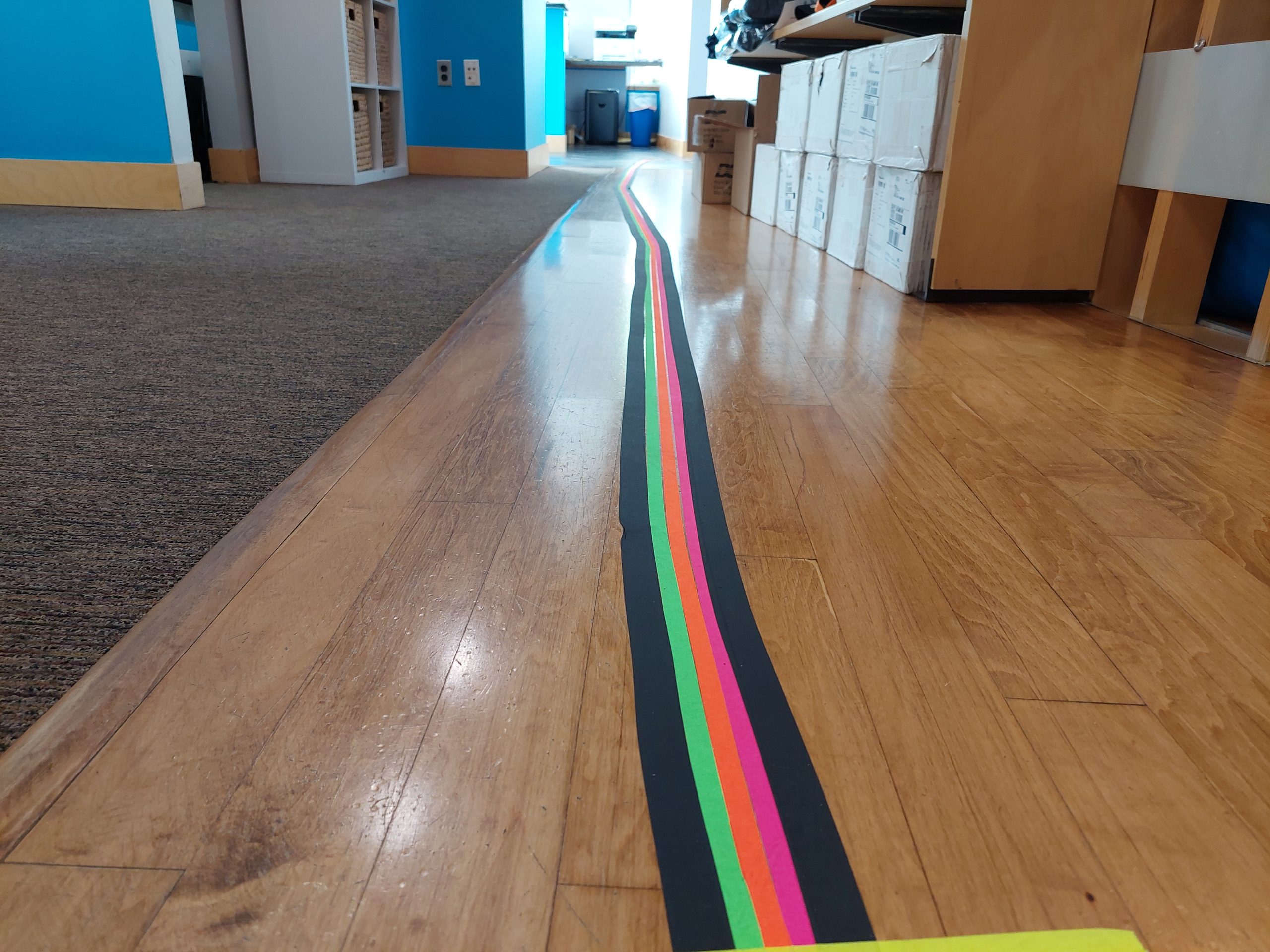
The goal for this lab day was to have an autonomous car race using some RC cars, single board computers (e.g., Raspberry Pi) or microcontrollers (e.g. ESP32), and sensors such as cameras or IR brightness detectors. The cars should follow the colorful race track of tape laid throughout the office.
Thanks to one of our awesome Tome Owls, our engineers had a general list of approaches they could take to complete this project. The end goal was the same, but the paths our teams took were very different.
- Machine Learning using Donkey Car
- This “no code” method allows you to train a model to follow the race track and then Donkey’s self-driving car platform handles the rest.
- OpenCV
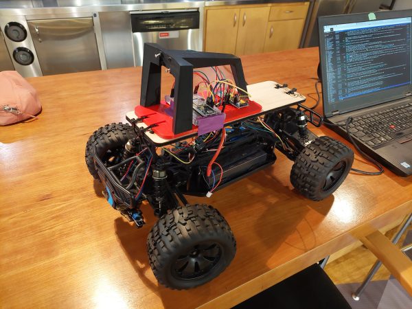
- Mount a camera to a RC car and use computer vision to process whether the car should go left, right, or straight. Use a Raspberry Pi to control the speed and steering of the car.
- ROS
- Run the robot as a micro-ROS node as a way to learn about ROS.
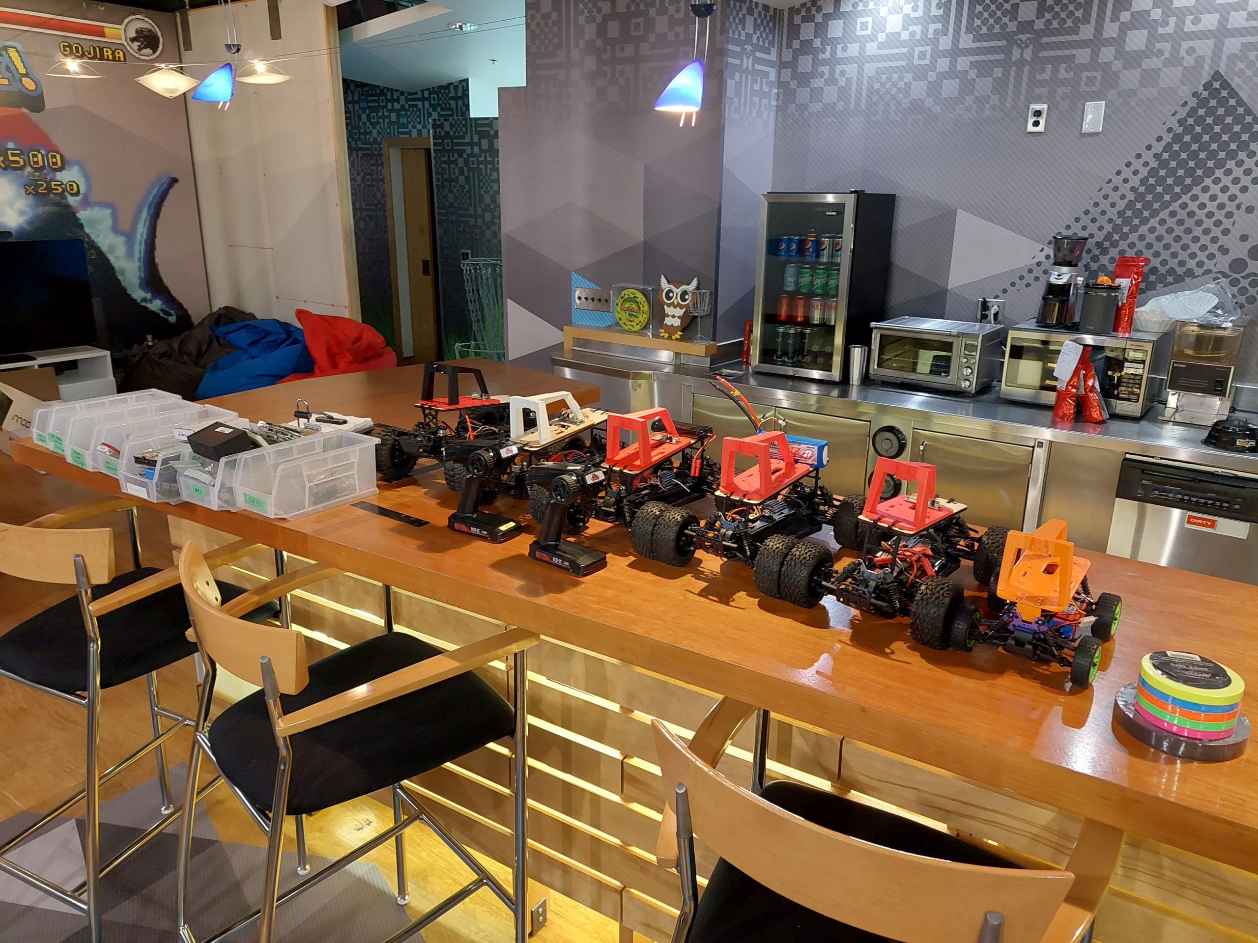
Car Setup
The remote controlled (RC) cars we used are 1/10 scale RC cars, mostly brushed and mostly with NiCd batteries. Donkey Car Pi mounts were used with laser cut adapter plates, because the Donkey Car Project is intended for 1/16 scale cars.
Approaches
DonkeyCar
On lab day, we used the donkey car method to try and program a robotic car to autonomously follow a path, which is a machine learning approach. We started by diving into the instructions provided by the donkey car. This is where we hit one of our first road bumps. When trying to install some of the necessary software onto our PC’s, it seemed to be installing a version newer than the one we needed. It fortunately worked for one of our members and so we continued on to the next steps. That included getting the software installed on a donkey car. Then we had to run the trials to collect training data by manually controlling the car. This also proved to be difficult. The controls on the computer were hard to work, and using a joystick had its own difficulties. Calibrating the motor and steering mechanisms took a bulk of our time. After persistence, we were able to figure out the controls. This is where we left off, and we would start back up by beginning the process to collect trial data next time. The project worked mostly as expected. We were expecting difficulties, and definitely encountered a handful, but with time, we were able to continue moving forward. We mostly used the official Donkey Car documentation that is on their website which provided good detail for completing this project.
OpenCV
This approach had two major components that we developed in parallel throughout the day:
- Computer vision algorithm that determines if the car needs to go left, right, or straight.
- Microcontroller that controls the car’s speed and steering.
We spent the morning struggling to set the appropriate GPIO pins on a knock-off Raspberry Pi. All of the prebuilt libraries were meant for true Raspberry Pis so they didn’t work well with our non-RPi microcontroller. We didn’t want to sink more time into building our own libraries so we found a spare Raspberry Pi 3 and got back to it. From there, it was fairly smooth sailing for this portion of the project. We were able to set the speed of the RC car and control the direction of the wheels using PWM (pulse-width modulation). The open issue now was determining at what angle to turn the wheels when going left or right.
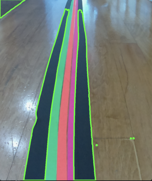
For the computer vision portion, we used Python and OpenCV. Unfortunately, we started off on the wrong foot. Instead of setting the car on the track and taking a few photos of a straight path, left turn, and right turn, we threw some tape on a piece of paper and ran our algorithm against that. Needless to say, we were tuning our algorithm against the wrong test set. Once we tested it with the camera mounted to the RC car, we realized we needed to start over with our algorithm. We got as far as detecting the contours of the path but we didn’t have enough time to write the logic that decides if the car needs to make a left or right turn. We plan to pick this back up for the next lab day and we’re confident we can make it to the finish line.
ROS
ROS, or the Robot Operating System, is a communication layer to connect sensors and control devices to logic.
The idea was to run micro-ROS on an esp32, and have it connect over wifi to a ROS agent to expose sensor data and control interfaces, and then have something else consume the sensor data and control the car.
Unfortunately, there is a bit of a learning curve with ROS and the project was put on pause when ROS stopped initializing on the esp32 for unknown reasons.
ROS Conclusions:
- It’s a neat communication layer, but for a simple project like this it’s definitely overkill
- It would be really cool to get the simulation stuff working
The car was fitted with two TCRT5000 IR reflective optical sensors to detect the line along with hall effect wheel tick sensors to measure speed.
Our Takeaways
- These RC cars are fast, proceed with caution.
- Spend a few minutes planning your approach rather than jumping right in.
- Future robotics projects would be really cool, and having the platform set up beforehand makes things smoother.
(Alexa Uljaj, Harman Tur, and Mark Furland contributed to this article)