
I find it amusing that in this era of abundant personal electronic communication tools, “everyone” still wants to be a broadcaster. More specifically, an FM broadcaster. This belief stems from observing the intense competition in recent years for FCC-issued Low Power FM broadcast licenses in local communities, and more empirically, from my Internet searches to find cool Lab Day projects that folks are building with the Raspberry Pi Foundation’s excellent five dollar computer, the Raspberry Pi Zero.
A number of search results described the steps to build a self-contained, software defined FM Transmitter using a RasPi Zero. The code not only transmits audio using a multiplexed stereo FM signal, but also transmits the subcarrier for the Radio Data System (RDS) data stream.
I was floored when I read these descriptions.
Given the broadcast FM Multiplex baseband spectrum (Fig. 1.) how can a simple RasPi Zero have processing power to generate all of those signals, with the correct phase, frequency offset and timing?
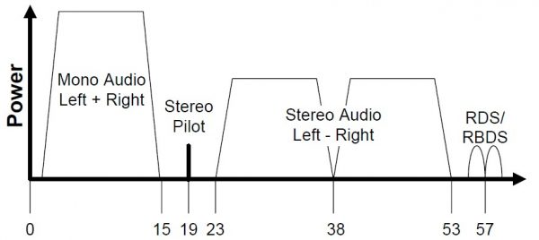
Fig. 1. FM Multiplex Baseband Spectrum, frequency is in kHz [1]
Four individuals contributed to this novel code.
The code’s original authors Oliver Mattos and Oskar Weigl (2012), write that the combination of their Python and C code “Uses the hardware on the Raspberry Pi that is actually meant to generate spread-spectrum clock signals on the GPIO pins to output FM Radio energy.” They wrote the code had been “hacked together over a few hours at the Code Club pihack.”
Later, Richard Hirst rewrote sections to use the RasPi’s Direct Memory Access (DMA) engine using DMA channel 0 which significantly reduced CPU usage. Interestingly, he implemented this by starting the DMA controller using memory owned by a user process. Hirst noted that if the user process exits without stopping the DMA controller “all hell could break loose” because the memory gets reallocated to other processes while the DMA controller is still using it. He wrote that his code caches Linux signals and resets the DMA controller before exiting.
Finally, Christophe Jacquet adapted the concept in 2014 to code the 57kHz Binary Phase Shift Keying (BPSK) subcarrier generator used for RDS.
The source code is available under the GPL, and can be downloaded from GitHub by searching for PiFmRds.
NOTE WELL THIS WARNING
DO NOT CONNECT AN ANTENNA TO THE RASPBERRY PI’s TRANSMITTER OUTPUT.
USE SHIELDED COAXIAL CABLE TO CONNECT DIRECTLY TO AN FM TUNER/RECEIVER’S ANTENNA INPUT.
The RasPi’s FM output power exceeds FCC allowable limits for unlicensed transmission in the FM band, and the generated signal has many off-frequency artifacts that can cause illegal interference. This is a project for research and study and NOT for transmitting music to your neighborhood.
The FCC is really, really good at finding spectrum violators.
The Proof is in the Broadcast
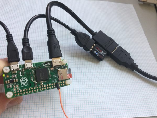
Fig. 2. The Raspberry Pi Zero with Wi-Fi dongle and adapters.
I installed a lean version of Raspbian on a Micro SD card and booted the Zero with a USB keyboard and HDMI monitor connected. Ironically, the cost of the mini-HDMI adapter, a mini USB adapter, a power supply, a Wi-Fi dongle, and a blank Micro SD card far exceeds the cost of the Zero itself.
Once logged in, I configured the network interface my local Wi-Fi credentials so I could complete the Raspbian updates and install the the PiFmRds code on the next reboot. Substituting a Wi-Fi dongle for the keyboard, I logged into the Zero using an SSH client, completed the updates and installation, then compiled the PiFmRds code. After a successful compilation, I uploaded a music file to the PiFmRds directory. I had on hand from a previous project some FLAC music files sampled at 96kHz / 24 bits and decided to try these.
I powered up my Sony XDR-F1HD tuner to 87.9 and connected the Zero’s physical pin 7 to the tuner’s antenna input using shielded coaxial cable, and ran the following command:
./pi_fm_rds -freq 87.9 -audio ./02-HeyNineteen.flac -rt "Tome RULES! Listen to Owlradio to WIN" -pi 7BE7 -ps "OWLRADIO" -ctl owlradio
The Program Information (PI) code shown here is a number that in the United States is translated into the station’s call letters. Here the hexidecimal code represents call letters “WOWL”. In Europe, the PI code is used to identify clusters of stations that are playing the same program, so when driving across a country, the receiver can automatically tune you the same program on a different station.
The RadioText (RT) is a short slogan that the receiver scrolls through. Typically Artist, title, album and similar text is transmitted by the station.
The Program Service (PS) text is a human readable call letters or 8 character word for display.
The -ctl owlradio parameter refers to a named pipe to dynamically change the Program Service name and the Radio Text.
Note that USB devices connected to the Zero won’t work while the transmitter code is running.
On the Air
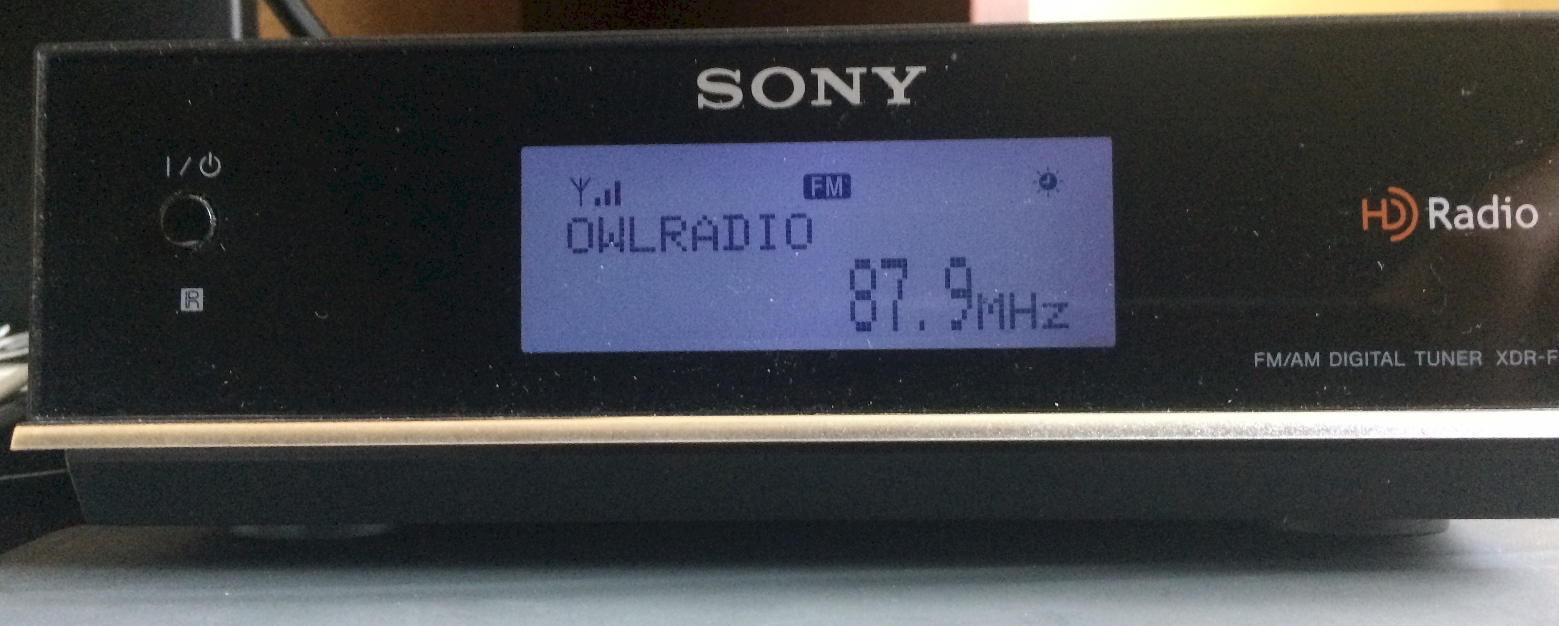
Fig. 3. Owl Radio is on the air!
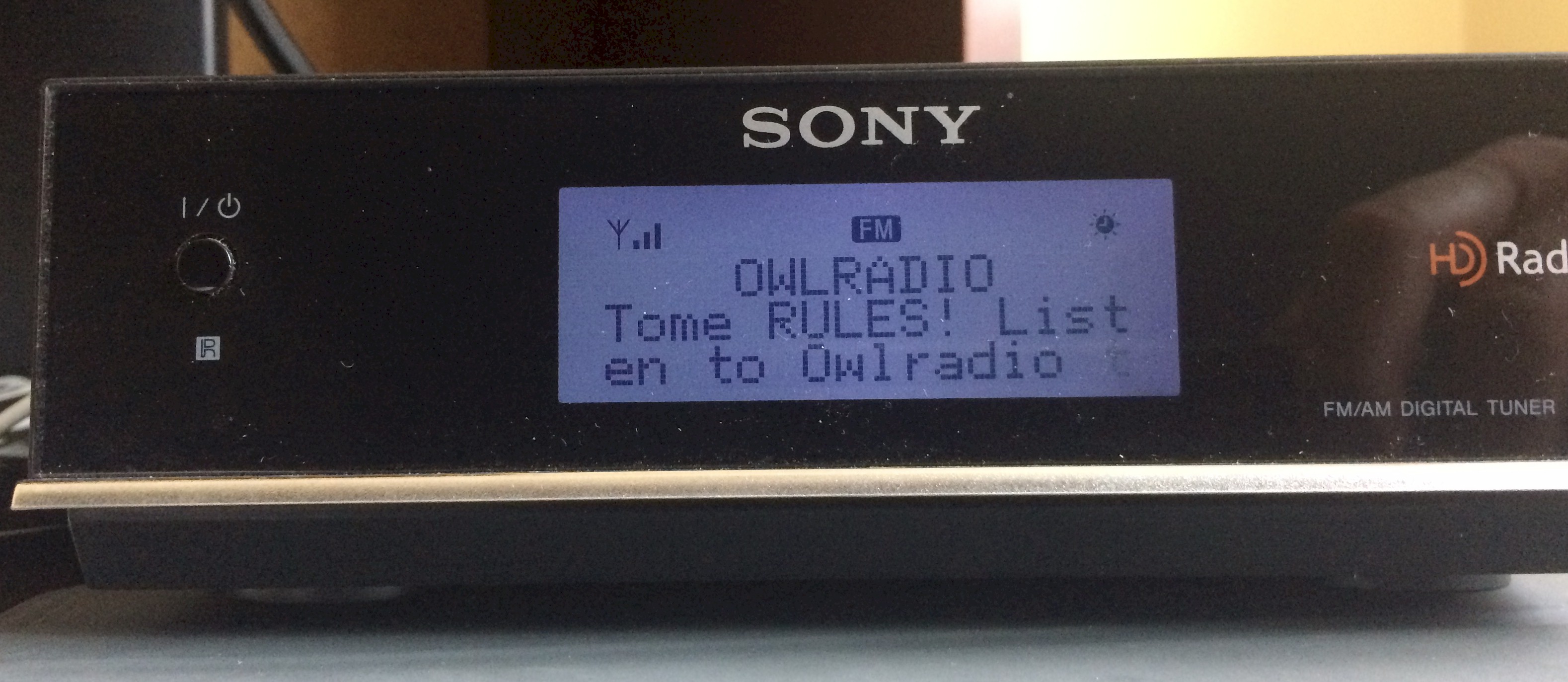
The RasPi transmitter started sending music over the “air” and the Sony tuner displayed the received radio text and program service name.
Fig. 4. The display shows the RadioText (Tome RULES!…) and the Program Service Name (“OWLRADIO”)
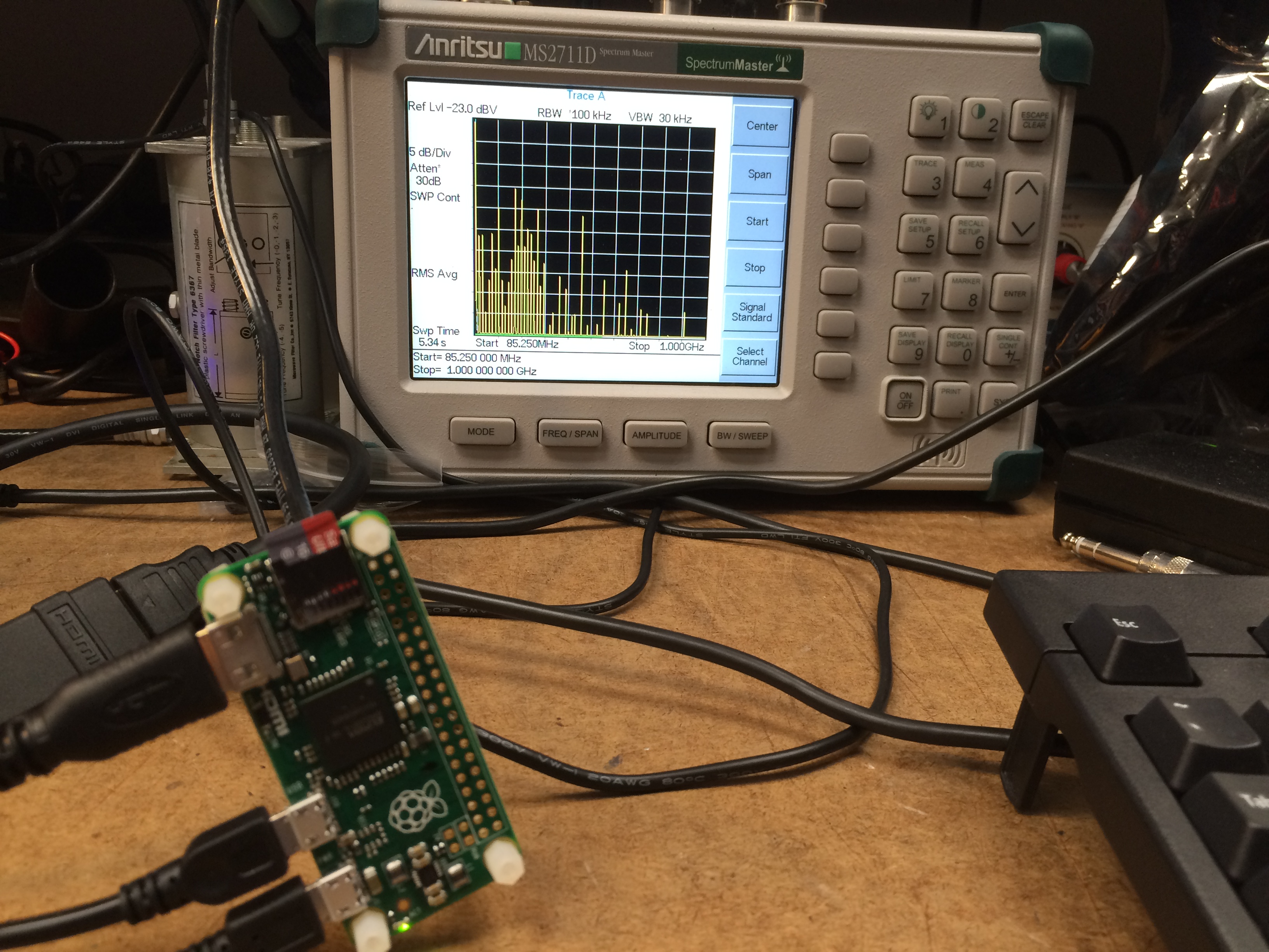
Fig. 5. The Zero connected to a RF Spectrum Analyzer. Here the Zero is transmitting at 85.25MHz (left side of display). The other vertical lines are RF spurious garbage from the Zero’s output, that extend to 1GHz.
Performance
The audio fidelity is definitely not broadcast quality; the high end hiss and frequency rolloff above 12kHz make for an acceptable listening experience, but inferior to a “real” and well-engineered broadcast station. Using a FLAC music file improved the fidelity, as compared to using, say, an MP3 audio file.
In addition, the Zero emits a number of spurious signals (“garbage”) all the way up to 1GHz.
Using a MacBe TRX011 RDS analyzer, I confirmed the received RDS data stream is complete and correct, as shown in the following TRX011 GUI screen shots.
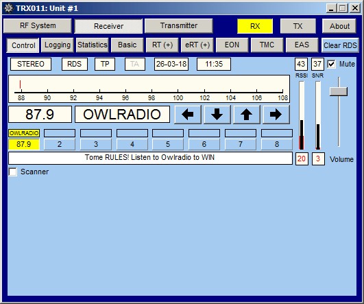
Fig. 6. The TRX011 analyzer control screen showing the RDS data. The PiFmRds software even transmits date and time in the correct RDS data block.
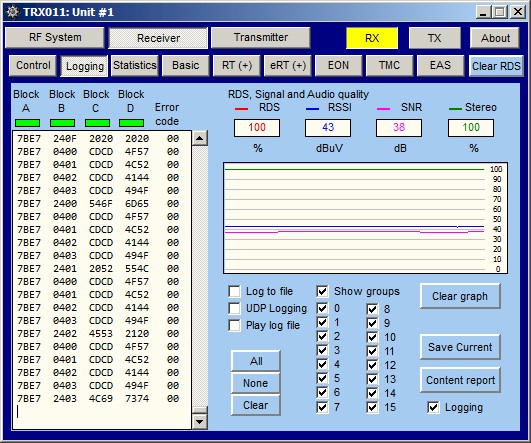
Fig. 7. The logging screen showing the four RDS data blocks. By standard, Block A constantly repeats the stations PI code so all FM RDS receivers have the station’s Program ID without waiting for it to be transmitted.
Conclusion
The PiFmRds project is a fun and excellent teaching tool on how to construct a useful software defined FM RDS transmitter using incredibly inexpensive hardware. While the aural output is not broadcast quality, it does reliably transmit the complex RDS data structures and really brings to life Edwin Armstrong’s 1933 invention of “Frequency Modulation”.
References
[1] Der, Lawrence; Frequency Modulation (FM) Tutorial https://www.silabs.com/Marcom%20Documents/Resources/FMTutorial.pdf; Silicon Laboratories Inc. (PDF)National Radio Systems Committee; NRSC-G300-B Radio Data System (RDS) Usage Guideline September 2014; http://nrscstandards.org/sg/NRSC-G300-B.pdf (PDF)